


Mastering Soldering Joints: Techniques, Tips, and Best Practices
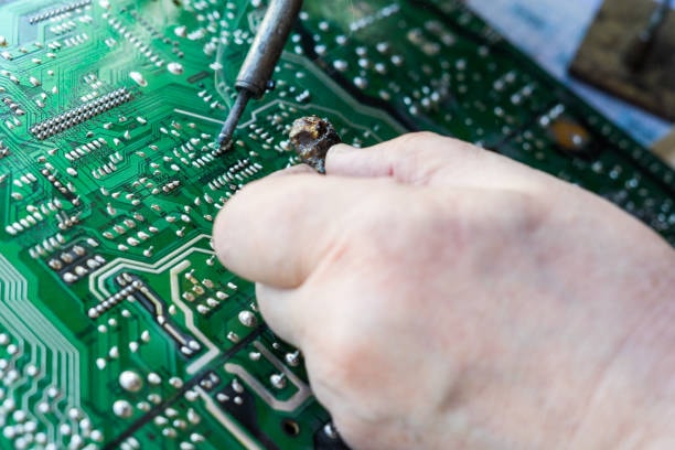
Soldering is one of the most simp- le and yet, crucial operations in electronics or anywhere else that you might require making good electrical connections. The ability to solder joints correctly will affect the overall quality of your project by its durability, no matter if you are a hobbyist, a beginner or an expert. This guide will contain information on the methods, procedures, and strategies that will enable anyone to prepare a near-perfect soldering joint each time.
What is Soldering?
Soldering joints is the method where two or more electronic components are brought together and bonded through the use of a filler metal which melts at low temperatures thus providing a strong bond both, electrically and mechanically. Usually tin and lead or a lead-free alloy, the solder melts when heat is applied, and the metal solidifies when it cools, thus providing the required mechanical connection.
What are the types of soldering joints
Types of Soldering Joints
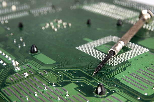
Through-Hole Soldering Joints
Through-hole soldering also entails placing the leads of the components into a through hole on a PCB and soldering on the other side. This type of joint affords mechanical rigidity and hence can be applied on connections containing parts which tend to be physically challenged in some way, for example, connectors and large capacitors. This technique, however, is particularly used in prototyping and repairs due to its reliability and ease in assessing mounted parts. Solder fills up the hole and also makes contact with the lead and the pad endowment providing strong and stable electrical connection.
Surface Mount Device (SMD) Soldering Joints

SMD soldering requires the placement of components directly to the PCB without putting them through holes on the board. This is widely used in present day electronics due to its advantages over conventional processes of fabrication in that multiple layers can provide the needed density of circuits and the total board area is kept to a minimum. SMD soldering is done on a soldering iron, hot air gun and the most effective one is the reflow soldering oven. Graphic pickup involves applying solder paste onto the pads, placing the component on top of it, and then using heat to melt the solder to make a connection. To prevent bridging of the bar and guarantee appropriate spacing of the cover bars, these joints have to be created carefully.
Butt Joints
Butt joints can also be made by putting the edges of two flat metal surfaces in contact and soldering them. This type of joint is not very popular in electronics circuits, although it can sometimes be implemented in splicing of wires, or in cases where metals are to be joined. Some basic facts that may affect the strength of a butt joint include area of contact between the joined pieces and amount of solder utilized. In this procedure, precise surface preparation through cleaning and the application of suitable flux are critical in facilitating the bond between the accident and substrate surface. butt joints are usually less strong compared with lap or through hole joints; however, the former may be quite suitable for items that are light or where there are very low levels of stress present.
Lap Joints
In lap joints, two pieces of metal are laid over one another and then they are soldered. It is mainly applied in bearing of wires or metal sheets and it is usually preferred when joining wires. It is known that lap joints have the advantage of creating a larger area for the solder to affix to creating a much stronger mechanical bond that butt joints allow for. Solder is deposited successfully in the overlapping area of the two pads creating a smooth cross-sectional flow as well as a 100% surface coverage. If performed correctly, then the lap joints have fine electrical conduction and mechanical clamping to be used widely for electronics and metal industry.
T-Joints
T-joints are those structures which are made when a metal is joined perpendicular to another metal and forms T shape structure at the joining area. This type of joint is employed frequently in joining structural frames, and supported in metalwork as well as, sometimes, in electronics to attach wires onto metal surfaces or lower layers of PCBs. T-joints offer good mechanical support and the structure will be able to support a great deal of load if soldering has been done correctly. This may necessitate intervention in order to guarantee that sufficient heat is available to distribute throughout the T-joint while at the same time supplying an optimal amount of solder flow.
Fillet Joints
Fillet joints are those solder connections that are used widely in the electronics industry to join the component lead and the PCB pad having the shape of a fillet. This joint shows a minimally disturbed, concave profile of the solder pad where it meets the substrate surface and shows proper wetting and surface adhesion. It is important in surface mount technology (SMT) and commonly made during the process of reflow soldering. The give a very good electrical interconnection and mechanical reinforcement of pads, with low probability of solder bridge construction between two neighboring pads. Solder volume and application of heat measures are critical necessary when developing ideal fillet joints.
Splice Joints
End joints are employed to join two wires side-by-side, end to end, in order to provide an unbroken conduction route. This type of joint is useful in wiring and cable arrangement especially in communication and data technology. There are a number of ways that splice joints can be made where among them are the Western Union splice, rat-tail splice and the twisted splice. Soldering is employed to complete these splices since it offers reliable electrical connection and mechanical reinforcement. These are necessary due to possibilities of short circuits and need for protection such as through both heat shrink tubing and electrical taping in splice joints.
Importance of Quality Solder Joints
A solder joint captures the electric conductivity, mechanical integrity, and reliability between electrical circuits. A proper soldering ensures strong interfaces to transfer signals across components, and any misconduct may lead to device malfunction.
Essential Tools and Materials
Soldering Iron
Select a soldering iron that has a temperature adjustment feature and one that should be used with a certain wattage for your project. This one is a great tip to be used in precise cutting and especially for lady’s finger nails or filing of nails.
Solder
Employ rosin-core solder for electronics . Lead-free solder is advised for medical and ecological concerns though lead-tin solder is preferable due to its better characteristics for novices.
Soldering Station
A kind of station with temperature control, and there is a holder for the probe and a sponge for cleaning it.
Flux
Flux enables to wash the surfaces and smooths the needed flow of the solder. This is most appropriate to give to work that needs to be rewound and repaired.
Desoldering Tools
Training is another very essential factor especially a desoldering pump or solder wick for correction of mistakes.
Tweezers and Pliers
These components prove useful if one requires clamping parts together.
Safety Gear
Secure your eyes using a safety glass apron for protection from hot solder splashes.
Soldering Techniques
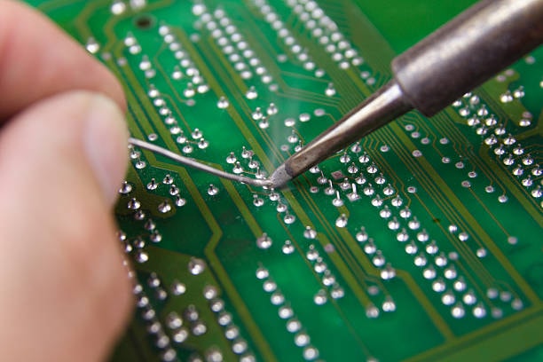
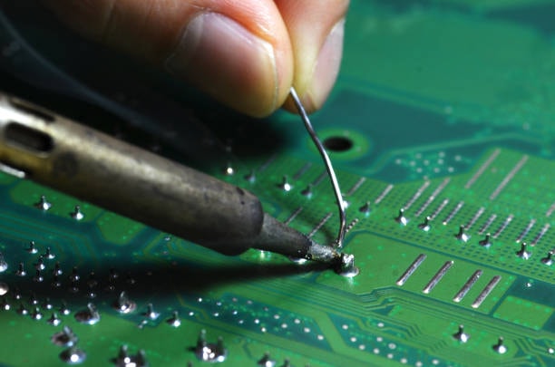
Basic Soldering Joint:
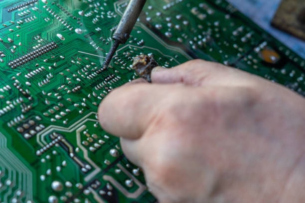
- Heat the Joint: Press the tip of the soldering iron on both the component lead and the corresponding pad on the PCB to heat the entire solder joints uniformly.
- Apply Solder: Solder the tip to the joint, not the direct application of solder onto the tip. The solder should ‘create a ring around the lead and the pad and it should do so with relative ease.
- Remove and Cool: Desolder and then deiron all the tips to minimize hindrance to the placing equipment. Another requirement is to allow the joint to cool before the movements are resumed.
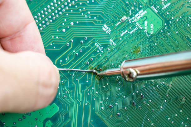
Through-Hole Soldering:
- Insert the component leads through the PCB holes Apply solder to the PCB where the component leads are inserted.
- Remember the regular process followed in soldering that is to make sure that the solder goes right into the hole as well as goes around the lead.
Surface Mount Device (SMD) Soldering
- Copper pads on the PCB should be coated with an appropriate amount of solder paste..
- Position the SMD component gently to the pads using the tweezers.
- Apply hot air or heat with the aid of a soldering iron to solder all four ends of the component to the joint.
Tips for Perfect Solder Joints
- Temperature Control: To avoid problems with the solder and other components, apply the correct temperature levels. Generally, around 350-400°C in case of lead containing solder and 370-420°C in case of lead free s p tempted solder.
- Avoid Cold Joints: In a cold joint, the solder doesn’t fill the gap as it is not molten and so the strength of the joint is compromised. Make sure that the meltpoint and the pad of the component lead are both uniformly heated.
- Solder Flow: See to it that the soldering material comes out in a continuous and even stream around the joint without creating a ball. Typically it should bow into a U shape, this the clincher that shows good contact.
- Cleaning: Always wet the tip of the soldering iron on a wet sponge or brass wire cleaner, to remove the oxide layer formed on the tip and enhance thermal conductivity.
- Practice: Practice makes perfect. Do basic soldering exercises to gain experience in soldering before moving towards the basic soldering methods used in various applications.
Common Soldering Issues and Solutions
- Cold Joints:Finally, heat the joint again and apply some flux so that the flux will flow to the joint.
- Bridging: If solder covers any two adjacent pads, then the best way to approach this is to use a desoldering pump or solder wick and remove all the extra soldering.
- Insufficient Solder: More solder should be applied so as to create a firm junction that will allow efficient electricity conduction.
- Overheating: Excessive heat may be dangerous to the parts and the PCB pads. Maintain the right temperature when soldering and do not take too much time during the soldering iron touches the joint area.
Advanced Soldering Techniques
- Reflow Soldering: In reflow soldering which is normally used in SMD component conformal coating the paste is applied on the pads on the board, then components are placed on the board and the whole assembly is heated through a convection reflow oven.
- Hot Air Soldering: Effective for solder reflow in SMD components, commonly used for repairing the product or for a small scale manufacturing.
- Soldering Fine-Pitch Components: Accurate work that often necessitates use of a loupe or any other tool for enlarged vision. If your circuit will require a lot of soldering, use flux, a fine solder wire, but be very careful because you can easily bridge between the solder points.
Safety Tips
- Ventilation: Smoking during soldering is not advised or even allowed in some places because the fumes resulting from the process can be toxic. The suggested mode of preventive measure includes working in a well ventilated area or using a fume extractor.
- Protective Gear: Use safety glasses and do not come into contact with the sides of the hot soldering iron.
- Proper Disposal: Regulate waste composed of soldering materials like lead based solder and fluxes according to the local legislation.
Conclusion
Soldering joints are incredibly important in electronics, and they require time and practice to get right because they are the weak links in any electronic circuit. Realizing appropriate hand or torch soldering approaches to various kinds of joints as well as following appropriate preparation and safety measures will certainly install you to make long-lasting and solid connections. Soldering is not a difficult task and even the professionals can have a poor soldering job when they fail to pay attention to details or are considering scenarios while practicing regularly.